4. Tutorial
Note
This tutorial refers to an early library. An update is in development.
Let’s go through a practical example, with a very simple protocol.
4.1. The Need
The gate of the house has an entry system, or intercom. Visitors push the bell button, and if all goes well after a brief conversation someone in the house let them in by pushing a gate release button. Residents have a code to let themselves in: they enter the code and the system releases the gate.
It would be nice to receive messages about these events, so that other events can be triggered (like switching on lights by night). It would also be nice to trigger the gate release independently of the entry system.
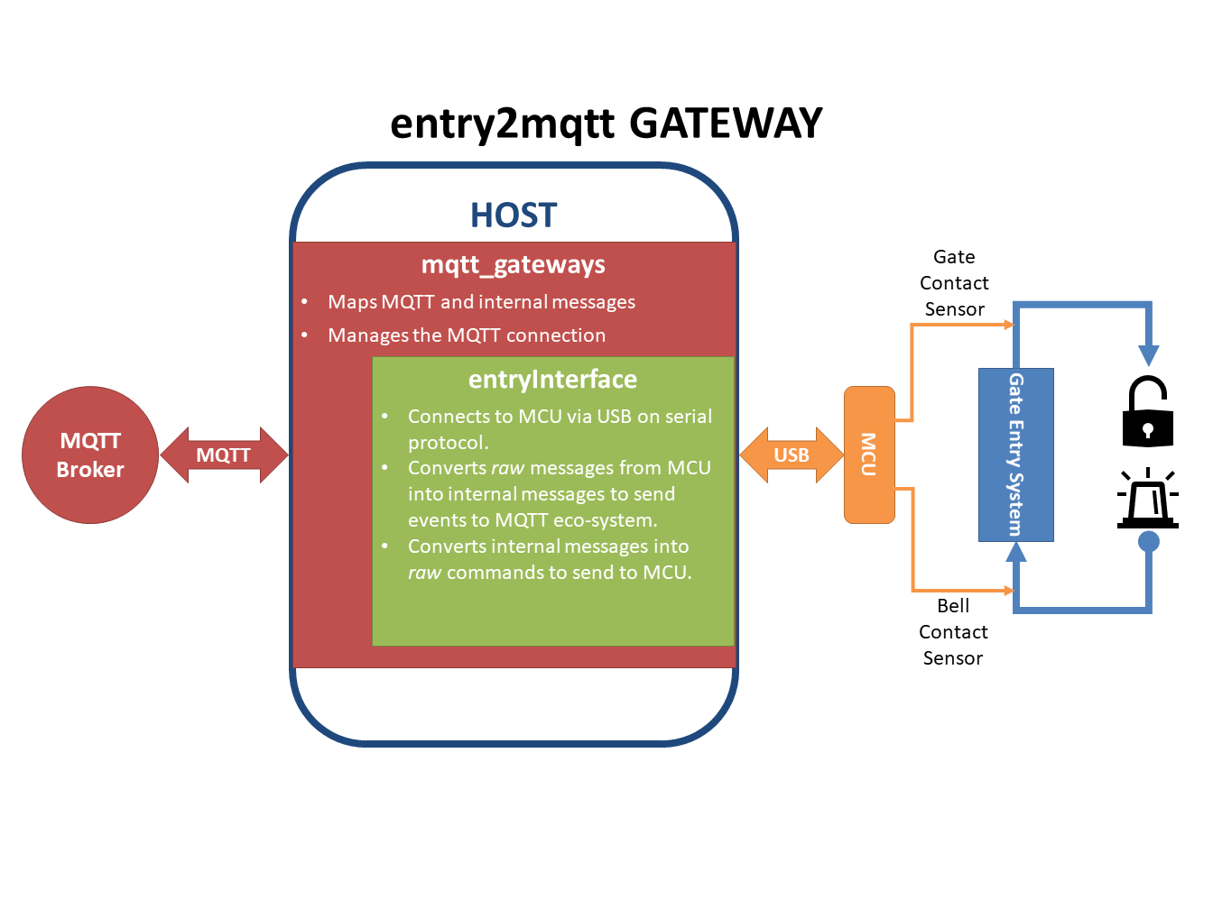
4.2. The Solution
We assume the entry system exposes the electrical contacts that operate the bell and the gate.
A micro-controller (an Arduino for example), can sense the electrical contacts going HIGH
or LOW and can communicate these levels to a computer through a serial port.
The micro-controller can also be told to switch ON or OFF a relay to release the gate.
We will call Entry System the combination of the actual entry system with the
micro-controller physical interface.
Note: a computer with the right sensors like a Raspberry Pi could sense directly the electrical contacts without being shielded by another board. However this use-case suits the tutorial, and is probably more reliable in the long run.
4.3. Implementation
The micro-controller is programmed to communicate with very simple messages for each event:
each message is a pair of digits (in ASCII), the first indicating which contact the message is
about and the second indicating its state.
With 2 contacts (the bell and the gate), and 2 states (ON and OFF),
there are only 4 messages to deal with: 10, 11, 20 and 21.
More precisely, the micro-controller:
- sends a message when a contact goes ON (
11or21) and another one when it goes off (10or20); - can also receive and process messages; in our case only the one triggering the gate release makes
sense (let’s say it is the message
21); we will assume that the micro-controller turns the gate release OFF automatically after 3 seconds, for security, so there is no need to use the gate release OFF message (20); similarly, there is no need to process the messages11or10as there is no need to operate the bell via MQTT.
The next step is therefore to code the interface for the computer connected to the micro-controller. Let’s call the interface entry. This will be the label used in all the names in the project (packages, modules, folders, class, configuration and mapping files).
4.4. The interface
The interface will be a Python package called entry2mqtt.
Let’s create it in a new folder entry with an empty module __init__.py.
In order not to start from scratch, let’s use the dummy interface as
a template. Copy the files dummy_start.py and dummy_interface.py from
the dummy package into the entry package, and change all the dummy instances
into entry (in the name of the file as well as inside the file).
The actual interface code has to be in the class entryInterface within the module
entry_interface.py.
It needs to have at least a constructor __init__ and a method called loop.
4.4.1. The constructor
The constructor receives 3 arguments: a dictionary of parameters and two message lists, one for incoming messages and the other one for outgoing ones.
The dictionary of parameters is loaded with whatever we put in the configuration file in
the [INTERFACE] section. It’s up to us to decide what we put in there. Here we
probably only need a port name in order to open the serial port. We will
create the configuration file later, but for now we will assume that there will be an
option port:what_ever_it_is in the [INTERFACE] section, so we can retrieve it in our code.
The constructor will generally need to keep the message lists locally so that the loop
method can access them, so they will be assigned to local members.
Finally, the constructor will have to initialise the serial communication.
Starting from the template copied above, the only thing to add is the opening of the serial port. Add at the top of the module:
import serial
(you need to have the PySerial library in your environment), and add the following line inside the constructor:
self._ser = serial.Serial(port=port, baudrate=9600, timeout=0.01)
The port variable is already defined in the template (check the code).
The baudrate has to be the same as the one set by the micro-controller.
Finally the timeout is fundamental. It has to be short enough so that
the main loop is not delayed too much. Without timeout, all the serial
exchanges will be blocking, which can not work in our mono-thread process.
Note
It is obviously possible to use natively multiple threads for the library to avoid the blocking calls issues. Indeed, the paho library is already doing so for its part. However this is not the case for now even if it might be implemented in the future.
4.4.2. The loop method
This method is called periodically by the main loop to let our interface do whatever it needs to do.
The loop method should deal with the incoming messages first, process them,
then read its own connected device for events, process them and stack in the outgoing list
whatever message needs to be sent, if there are any.
Use the code in the template to read the incoming messages list and add the following code to deal with the case where the message is a command to open the gate:
if msg.action == 'GATE_OPEN':
    try:
        self._ser.write('21')
    except serial.SerialException:
        self._logger.info('Problem writing to the serial interface')
Always try to catch any exception that should not disrupt the whole application. Most of them should not be fatal.
Then read the serial interface to see if there are any events:
try:
    data = self._ser.read(2)
except serial.SerialException:
    self._logger.info('Problem reading the serial interface')
    return
if len(data) < 2:
    return
If there is an event, convert it into an internal message and add it to the outgoing message list:
if data[0] == '1':
    device = 'Bell'
    if data[1] == '0':
        action = 'BELL_OFF'
    elif data[1] == '1':
        action = 'BELL_ON'
    else:
        self._logger.info('Unexpected code from Entry System')
        return
elif data[0] == '2':
    device = 'Gate'
    if data[1] == '0':
        action = 'GATE_CLOSE'
    elif data[1] == '1':
        action = 'GATE_OPEN'
    else:
        self._logger.info('Unexpected code from Entry System')
        return
msg = internalMsg(iscmd=False, # it is a status message
                  function='Security',
                  gateway='entry2mqtt',
                  location='gate_entry',
                  device=device,
                  action=action)
self._msgl_out.append(msg)
Finally, let’s send a command to switch on the light in case the gate was opened:
if data == '21':
    msg = internalMsg(iscmd=True,
                      function='Lighting',
                      location='gate_entry',
                      action='LIGHT_ON')
    self._msgl_out.append(msg)
That’s it for the basic logic.
4.4.3. Other coding strategies
The resulting code is as simple as it can be. There are clearly more advanced coding strategies to make the code more elegant and ultimately easier to mantain and upgrade.
For example, the class can be defined as a subclass of the Serial class, as this would reflect well what it actually is, i.e. a higher level serial interface to a specific device.
Another possibility is to code the conversion of the messages from the serial interface into internal messages through lookup tables (dictionaries) instead of nested ifs.
There are always better ways to code, but it is important to note that, as the loop is supposed to run fast and is the piece of code that will run forever, it is worth investing some time on how to make that part more efficient.
4.4.4. The map file
The mapping feature is disabled by default.
This means that all the keywords introduced earlier in the code (the commands GATE_OPEN, GATE_CLOSE, BELL_ON and BELL_OFF, as well as the location gate_entry and the
function identifiers Security``and ``Lighting) will all be passed on as is to the MQTT
messages, with exactly the same spelling and the same capitalised letters, if any.
This might be acceptable if there are only a few devices and gateways in the MQTT network
and the vocabulary stays quite small. But if the network grows and evolves, inevitably
changes will happen and it becomes inpractical to have to change the code any time an
identifier in the MQTT vocabulary had to change. That is where the mapping feature steps in.
The mapping feature can be enabled in the configuration file, in which case a file location for the map needs to be provided:
...
mapping: on
mapfilename: /the/path/to/your/mapfile/filename.json
The map file location option is subject to the various rules for file paths used in this library. In a nutshell, if the path is absolute there is no ambiguity, if it is relative the library will try the path starting from the configuration file directory first, then try the current working directory of the process, and finally the directory of the launching script.
The mapping file is a JSON formatted file with 2 objects (the root of the MQTT
messages and a list of topics to subscribe to) and up to 8 dictionaries, 1 for each
characteristic that can potentially be mapped. For each characteristic, a maptype needs to
be provided (it can be either none, loose or strict) and then an actual map, if
the maptype is not none.
For our interface, we assume we want to map all the data, as shown in the table:
| Characteritic | MQTT Keyword | Interface Keyword |
|---|---|---|
| function | security | Security |
| function | lighting | Lighting |
| gateway | entry2mqtt | entry2mqtt |
| location | frontgarden | gate_entry |
| device | gate | Gate |
| device | bell | Bell |
| action | gate_open | GATE_OPEN |
| action | bell_off | BELL_OFF |
| action | bell_on | BELL_ON |
| action | light_off | LIGHT_OFF |
| action | light_on | LIGHT_ON |
| action | gate_close | GATE_CLOSE |
The map file would then look like this:
{
    "root": "home",
    "topics": ["home/security/+/frontgarden/+/+/C",
               "home/+/entry2mqtt/+/+/+/C",
               "home/+/+/+/entrysystem/+/C"],
    "function": {
        "map": {"security": "Security", "lighting": "Lighting"},
        "maptype": "strict"
    },
    "gateway": {
        "map": {"entry2mqtt": "entry2mqtt"},
        "maptype": "strict"
    },
    "location": {
        "map": {"frontgarden": "gate_entry"},
        "maptype": "strict"
    },
    "device": {
        "map": {"gate": "Gate", "bell": "Bell"},
        "maptype": "strict"
    },
    "sender": {"maptype": "none"},
    "action": {
        "map": {"gate_open": "GATE_OPEN",
                "bell_off": "BELL_OFF",
                "bell_on": "BELL_ON",
                "light_off": "LIGHT_OFF",
                "light_on": "LIGHT_ON",
                "gate_close": "GATE_CLOSE"
        },
        "maptype": "strict"
    },
    "argkey": {"maptype": "none"},
    "argvalue": {"maptype": "none"}
}
Save it in a file named entry_map.json.
A few comments on this suggested mapping:
- most of these keyword mappings only change the case or even nothing; this is for illustration purposes anyway, but in general it might still be good discipline to list all the keywords in a mapping to have in one view what the interface can deal with or not. Then if one day some MQTT keyword needs to change, everything is ready to do so.
- an important choice to make is the
maptypefor each characteristic. If it is set tostrict, it will enable to filter messages quite early in the process and alleviate the code of further testing. In our example, even if thegatewaymap has only one item, which is even the same on both sides, setting themaptypetostrictensures that only that keyword is accepted, and any other one is discarded. This is obviously very different from setting themaptypetonone, in which case that only keyword would still be accepted and left unchanged, but so would any other keyword.
4.5. Wrapping it all up
Once the interface is defined, all is left to do is to create the launch script and the configuration file. Those 2 steps are easy using the templates.
Copy the dummy project launch script dummy_start.py and paste it
into the entry directory.
Change every instance of dummy into entry`.
If all the naming steps have been respected, the script entry_start.py just created
should work.
To create the configuration file, copy the configuration file dummy2mqtt.conf from
the dummy package and paste it in the folder entry with the name entry2mqtt.conf.
Edit the file and enter the port option under the [INTERFACE] section:
[INTERFACE]
port=/dev/ttyACM0
Obviously input whatever is the correct name of the port, the one shown is generally the one
to use on a Raspberry Pi for the USB serial connection. If you are on Windows, your port
should be something like COM3.
If you went through the installation process, then the MQTT parameters should already be set up, otherwise do so. Other parameters can be left as they are. Check the configuration guide for more details.
4.6. Launch
To launch the gateway, just run the launcher script directly from its directory:
python entry_start
Done!